Diamond Springs & Western
Stub Turnout
Stub Turnout Construction
Introduction
The last of the turnouts I scratchbuilt for my first D.S.&W. layout was a stub-turnout. I expected this to be quite complicated and therefore thought I'd need practice before starting. Absolutely wrong! This turnout was the best and most flawlessly operating turnout I had on my layout.
Most of the ideas came from several articles in the hobby press so I don't claim them to be my invention. For further reference the following articles seem most useful:
- Motorized Stub Turnouts in Sn3 by William J. Bussaca / Narrow Gauge And Shortline Gazette Jul/Aug 91
- Modeling a stub switch by Carl Caiati / Model Railroader Jan 91
Instructions
-
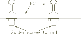
 Solder a small screw to the underside of each movable stub rail.
I did use metric 1mm screws, but anything small
enough to be hidden under the rail's base should work.
Using screws with a tapered head will allow sinking them into
the tie more easily.
- Cut a tie from printed circuit board ( PC ) acting as a tie bar.
- Carefully mark two holes on the tie, with the distance exactly your gauge. Drill slightly larger than the screws you soldered to the rail. Countersink with a larger drill so the screws soldered to the approach rails can be sunk into the tie. The rails should touch the tie.
- Screw the rails to the PC tie. Don't fasten the nut to strong. The rails should still be movable without being too loose. Secure the nut with a small drop of CA or solder.
- Cut a groove into your trackbase. The groove should be large enough to allow your tie bar to move freely.
- Fix the approach rails in place. I didn't nail the last 2" to allow for easy bending. This works perfect for code 55 rail. If you're using larger sizes, you might have to experiment here a bit.
- The rest of the turnout construction is standard practice. File the top inside of all rails to a shallow angle. This will allow for tiny misalignments.
- I use Switchcraft turnout motors on my layout. Special mounting is not necessary for a stub turnout. I made two stops to align the rails properly by glueing small pieces of scrap styrene in place. Later I learned that soldering pieces of brass wire on the outer side of both stock rails is much easier.
- Since there is no electrical contact, the frog has to be powered by an auxiliary switch thrown by the turnout motor.
