Diamond Springs & Western
HOn30 Hopper
Introduction
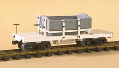
The inspiration for the project came from a drawing of a proposed Yosemite Shortline hopper car by Gary Caviglia, published in the Narrow Gauge And Shortline Gazette issue Mar/Apr 1988. Finding a British 009 kit did ease the construction of the car very much, as it provided the hopper itself. The rest is basic styrene construction without any major difficulties.
Drawing
Sources
The kit in question is a Snailbeach District Railways Hopper Wagon, no. DM6P and manufactured by:
      Parkside Dundas
      Millie Street
      Kirkcaldy, Fife
      Scotland KY1 2NL
A possible source in the U.S. is
      International Hobbies
      10556 Combie Rd., Suite 6327
      Auburn, CA 95602
      Phone/Fax: 916/268-8715
      Web: Homepage
Preparation
I did use Evergreen styrene strips and sheet for the kit. All measurements given are scale dimensions. I feel that wood grain is hardly visible in HO scale, especially on painted models. I sand all my styrene parts slightly to remove that very accurate look of the material but don't try to add knotholes etc..
Hopper
- Assemble the hopper itself as suggested in the supplied instructions. I found that the parts don't fit very well, so a lot of testfitting and sanding is necessary.
- Build a small box from 12"x2" strips for the chute at the bottom of the hopper.
- Cut four pieces of 4"x4" each 4' long. Glue these side stakes to the hopper on the outside of the iron straps. Make sure they are rectangular to the top.
Frame
- Evergreen 4"x8" strips are used for the side- and endbeams. Cut two endbeams each 6'6" long and two sidebeams 18'4" long. Assemble them to a small rectangle. Make sure the sidestakes on the hopper fit to the outside of the sidebeams.
- Next cut the planking for both ends from styrene siding. Both pieces should be 6'6"x4'8". Glue them to the ends of the frame you built up in the last step. This will stabilize the frame and ease fitting of the centerbeams.
- For the centerbeams a 1"x6" and a 2"x6" are laminated together to form a 3"x6" beam. Cut two pieces 18'4" long. Glue them in place 1'3" from the outside of the sidebeams.
Adding the Hopper
- Now glue the hopper assembly to the frame making sure the hopper is centered lengthwise and touches the outer centerbeams.
- The two inner centerbeams are fitted in place next. They are situated 3' from the outside. In case you plan to add a load to your hopper, four pieces are needed, fitted in place between the endbeams and the hopper. In case no load is planned two additional pieces should be glued to the inside of the hopper, simulating the beams going through the whole length of the car.
- Cut four pieces of 4"x4" each 4'6" for the remaining stakes. Glue these stakes to the hopper and the inside of the outer centerbeams. See drawing.
Trucks
- Glue a piece of 12"x2" to the underside of the frame centered at each end to serve as mounting pads for the couplers.
- Add the bolsters making sure the couplers have the correct height. The drawing above indicates the position of the ubiquitous Grandt Line SR&RL trucks.
Details
- Add Grandt Line NBWs to the side- and endstakes as indicated on the plan and to the endbeams.
- The tierods are formed from brass wire and glued in place.
- Glue a brakewheel to a piece of brass wire. The wire should be a bit more than 2' long. Drill a hole of the appropriate diameter for the wire in the middle of the frame, right next to the hopper. Glue the staff in place extending 2' above the deck.
- Add a brakewheel, brakehanger and ratchet from a Grandt Line brake kit to the same end of the car. The plans don't show an airbrake system.
- Although the prototype plan doesn't indicate them you can add steps.