Diamond Springs & Western
Worldwide NG Links
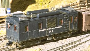
DS&W Oil-Electric Engine #100
Introduction
 I was asked on the HOn30 list to give some more details on construction of my
DS&W #100 oil-electric engine. As this was written years after the model
was finished, this is
done from memory with some possible errors. So check every step and make
sure it makes sense to you.
I was asked on the HOn30 list to give some more details on construction of my
DS&W #100 oil-electric engine. As this was written years after the model
was finished, this is
done from memory with some possible errors. So check every step and make
sure it makes sense to you.
While this engine is freelanced, similar ones existed. Bruce Pryor has a photograph and a drawing for a Chiriqui Boxcab on his Narrow Gauge From Off The Beaten Path website.
My model is done for HOn3 with a Jonan drive underneath. In my case the distance between the truck centers is 2 3/16" and the overall length of the model is about 4 1/8". For HOn30 there is a wealth of N scale diesels available that could be the base for a similar project. If you select a drive of notably shorter wheelbase, you'll have to adapt the sides for a shorter body.
Besides the drive you'll need one Athearn 34' Cupola Caboose Caboose ( No. 1249 ), undecorated preferred, some styrene sheet ( 0.040" thick ) and styrene strips of different sizes.
Cutting the body
Using a new sharp blade in your hobby knife the body has to be cut apart. Remove the roof by cutting from the inside of the body. This will leave thin rivet strips on the sides that can be carefully cut off. Keep them as they come handy for covering an problem zones created while splicing together the sides. Then, again from the inside, cut out both ends. I used a doors and one end window for each side from the ends for re-usage on the sides and discarded the rest.
Sides
Now create two symmetrical side parts by cutting and slicing the sides of the
caboose. These side parts determine the overall length of your model, so make
sure your drive fits underneath. In most cases it might be easier to start from
two caboose kits but I prepared my model from one. Good planing pays in this
step. The doors should go into one end on each side so that your personnel can
access the cab easily.
Fill in all rivet lines destroyed during this process with bits and pieces of the strips
from the first step.
Front
This part determines the width of your finished model. In my case the scale width is 8'9". Determine the correct dimension by measuring some rolling stock you have. In HOn30 something between 6'6" and 7'9" would probably be reasonable. Cut a strip of styrene from 0.040" sheet material long enough for both end parts. Cut that part in half. That way it is made sure that both halves are of identical width. Temporarily glue those parts together using white glue or Scotch tape. Then file the tops to a round shape similar to the curvature of the caboose roof. Determine the required height from your sides plus the height of the coupler beams ( 1/8" in my case ) and cut the parts accordingly. Split the parts again.
Front Windows
 After the parts are correctly shaped, it is time to add the openings for the
windows. The most easy way is to cut the fronts with a cutting line exactly
below the windows. Cut out the openings from the upper half of the fronts. See
drawing for details. This procedure is much easier than removing the windows
from the solid parts and the cutting line will be taken care of in the next
step. Glue the parts together.
After the parts are correctly shaped, it is time to add the openings for the
windows. The most easy way is to cut the fronts with a cutting line exactly
below the windows. Cut out the openings from the upper half of the fronts. See
drawing for details. This procedure is much easier than removing the windows
from the solid parts and the cutting line will be taken care of in the next
step. Glue the parts together.
Next step will be to add the window framing. Use strip styrene to line the openings. 0.015" x 0.060" strips work great with a 0.040" front, use different sizes if you used other thickness for the fronts. Once the framing is in place, the interior frames will be added. The correct dimensions can be easily determined by temporarily fixing some sheet styrene to the front parts and tracing the existing window openings with a pencil. The thickness of the pencil will lead to the markings lines being exactly parallel to the frame put the overall size is slightly smaller. Make sure that you hold the pencil at an 90 degrees angle all the time. Cut out the windows and glue the part to the back of the front.
Finishing the front parts
On my model I used the Vintage Reproductions rivet tool and foil. Mark the rivet lines on both sides of the window openings and a small distance from the bottom. Impress the rivets and cut out the openings for the window frames. Glue the rivet overlay onto the front parts and you're finished with that step.
Assembling the body
Now it's the time to put all the body parts together. This is an easy step. Create two L-shaped halves by glueing together a side and a front. Use a straightangle to make sure that the positioning is correct. It doesn't hurt to use some strip styrene ( eg 0.040" x 0.040" ) to the inside in order to strengthen the joint. Once these joints are solid you can assemble the two halves to create the complete body. Cut a rectangle from 0.020" styrene sheet that is slightly long and wider than the finished body. Pre-bend this part lengthwise by dragging it across the edge of your worktable. This will become the roof. Glue it to the body and hold it in place until the glue has set using rubber bands. Do apply the bands at the ends only as you will get a sagged roof otherwise. While this might look great on an old boxcar we do not want it on this model. Add the coupler beams from 1/16" x 1/8" strip styrene.
Adding the body to the drive
This step will depend one the model you use for your drive. For most hood units, the best way would be to remove the original cab and cut a styrene rectangle that snuggly fits into your new body. Cut an opening into that rectangle that allows it to rest on the running boards of your N scale diesel. Later you can hold the body in place using CA or maybe even a product like Blue Tac ( sp ? ) that is used for holding posters to the wall.
Fun part - detailing
Now comes the part where you can let your creativity flow - adding the details. I won't go into a lengthy discussion on what I've added. Instead I'd like to give you some pointers here:
- you'll need a bell and whistle, eg. steam engine detailling parts.
- an exhaust opening in the center line of the roof. I found a oldtime smoke stack in my parts box from which only the top is still visible.
- the roofwalk parts form the caboose can be used to add a roofwalk here. As there is the exhaust in the middle the roofwalk could be added to the left and right. Use strip styrene to fill gaps.
- air cylinders can easily be prepared from styrene tubes or wood dowels. The riveting can be added in a similar way to the one used for the fronts.
- the cooling system ( at least that what I suppose it is ) can be built up from corrugated material left over from a structure project or from individual styrene or brass rods that are bent and glued together.
- a ladder is needed to allow personal to climb onto the roof. I've used individual steps bent from brass but using a ladder detail will be easier ( eg. Grandt Line ).
- don't forget the headlights, frontsteps, coupler lift bars ...
Painting and weathering
Again painting as an area where you can add your own ideas. Except from dust
and some road grime I wouldn't add to much weathering. This time of engine
became available in the 1920's so most probably would be quite new for most
narrow gauge modeling era's ( and besides they would be the managers and
constructors pride and kept well in shape ).
So that's it - fix the finished body to your drive system and enjoy your first
( or at least newest ) piece of motive power. Let me hear or better see what
your variation of this approach looks like!